From CAD File to Finished Part: A Step-by-Step Guide to the Prototype Machining Process in 2025

When an engineering team finalizes a CAD model and prepares to move toward physical production, the distance between digital design and a usable part is rarely straightforward. Material behavior, tolerance stacking, surface requirements, and geometric complexity all introduce variables that a file alone cannot predict. This is where the machining of early-stage parts becomes critical — not as a formality before production, but as a structured process that validates whether a design is ready to scale, manufacturable under real conditions, and safe to commit to tooling investment.
In 2025, the pressure to move from concept to qualified part faster than before is real. Supply chain constraints, compressed product development cycles, and tighter regulatory expectations in industries such as aerospace, defense, and medical devices mean that early-stage machining decisions carry more downstream consequence than they once did. Understanding how that process actually unfolds — from the initial review of a CAD file through to a finished, inspected component — helps engineers, procurement teams, and project managers make better decisions at every stage.
What Prototype Machining Actually Involves
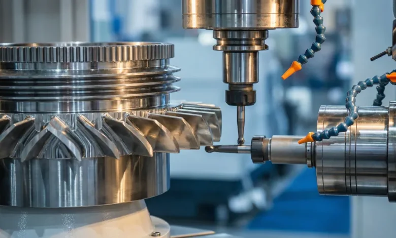
The term prototype machining refers to the controlled subtractive manufacturing of early-stage or pre-production parts, typically in low quantities, to verify a design before it enters full manufacturing. This is not simply running a CAD file through a CNC machine. It involves a coordinated series of decisions about material selection, fixturing, toolpath strategy, surface finish requirements, and inspection criteria — all applied to a part that may have never been physically produced before.
For engineers working in sectors where performance margins are narrow, engaging with a team experienced in prototype machining early in the development process reduces the risk of discovering manufacturability problems after significant design resources have already been committed.
The scope of what qualifies as prototype machining varies by industry. In some contexts, it means producing a single aluminum mock-up to confirm assembly fit. In others, it means machining a small batch of components from production-equivalent material to validate a design under real load and thermal conditions. Both purposes are legitimate, but they require different process setups and inspection rigor.
The Role of Design Intent in Process Planning
Before a machine is programmed or a workpiece is clamped, the machining team needs to understand not just what a part looks like on screen, but what it is expected to do in service. A feature that appears straightforward in a CAD model — a bore, a slot, a threaded hole — may require specific sequencing, tooling, or post-machining treatment depending on the part’s functional requirements.
Design intent shapes how tolerances are prioritized during machining. When a drawing specifies tight tolerances on a particular datum or mating surface, the machinist and process engineer must understand why those dimensions matter, not just that they appear on the drawing. Without that context, process decisions may inadvertently deprioritize the features that carry the most functional consequence.
Reviewing the CAD File Before Any Cutting Begins
The CAD file review is the first formal step in translating a digital design into a machining plan. During this stage, the manufacturing team examines the geometry for features that may present challenges — thin walls, deep cavities, undercuts, or surfaces that require multi-axis access. This review is not about judging the design; it is about identifying where the machining process will need special attention and whether any modifications should be discussed before setup begins.
This step also involves checking file format compatibility, confirming that tolerances are explicitly documented rather than assumed, and identifying whether the part requires a single setup or multiple fixturing positions. Multi-setup parts introduce cumulative error risks at datum transfer points, which affects how inspection plans are structured later in the process.
Design for Manufacturability Considerations
Design for manufacturability analysis during file review often surfaces issues that are straightforward to correct before machining begins but expensive to address after a part has been produced. An internal radius that is smaller than standard tooling can accommodate, for example, either requires specialized tooling — which adds cost and lead time — or a minor design revision that preserves function while simplifying the machining process.
These conversations between the engineering team and the machining team are where prototype machining provides its most underappreciated value. The dialogue at this stage often improves the final design in ways that benefit not just the prototype run but the eventual production process as well.
Material Selection and Its Effect on Machining Strategy
Material selection for a prototype part is not always identical to what will be used in production. In some cases, a more machinable substitute is used to validate geometry before committing to a more costly or difficult-to-machine production material. In other cases — particularly where mechanical validation is the goal — the prototype must be machined from the same material, heat treat condition, and stock form as the intended production part.
According to standards published by ASTM International, material traceability and certification are increasingly required for components used in regulated applications, even at the prototype stage. This has changed how many organizations approach early-stage machining, treating even first-article parts with the same material documentation discipline applied to production runs.
How Material Properties Shape Toolpath and Fixturing Decisions
Harder or more abrasive materials wear tooling more quickly and generate more heat during cutting, which affects both dimensional accuracy and surface integrity. Softer or more ductile materials may deform under clamping pressure if fixturing is not designed carefully. Exotic alloys used in aerospace and energy applications often require specific cutting parameters, coolant strategies, and tool coatings to produce acceptable results.
These realities mean that a machining team experienced with the target material class is more likely to produce a prototype that accurately represents what a production process would yield. A prototype machined under inappropriate parameters may technically match drawing dimensions while exhibiting surface conditions or residual stresses that would not appear in production — creating a false sense of design validation.
Programming, Setup, and the First Cut
Once the file review is complete and material is confirmed, the machining team develops the CNC program and fixturing plan. Programming involves translating the CAD geometry into toolpaths that the machine can execute, accounting for tool selection, cutting sequence, feed rates, and approach strategies that minimize vibration and heat generation.
Fixturing — how the workpiece is held during machining — is one of the more consequential decisions in the entire process. A poorly designed fixture introduces movement or deflection under cutting forces, which translates directly into dimensional deviation on the finished part. For prototype machining specifically, where quantities are too low to justify custom dedicated fixtures, the team often relies on modular fixturing systems or soft jaws that must be carefully validated before the first cut.
First Article Verification During Machining
On a first-article prototype, experienced machining teams often pause at intermediate stages to measure critical features before completing the part. This in-process verification allows the team to identify dimensional drift or unexpected material behavior before it compounds into a non-conforming finished part. The ability to catch and correct problems mid-cycle is one of the structural advantages of prototype machining over jumping directly to high-volume production.
Inspection and Documentation of the Finished Part
Once machining is complete, the part enters a formal inspection process. Depending on the application and the customer’s requirements, this may range from a manual dimensional check against drawing callouts to a full coordinate measuring machine scan that maps the part surface against the original CAD model.
Inspection at the prototype stage serves a dual purpose. It confirms whether the machined part meets the drawing requirements, and it generates data that informs whether the design itself needs revision. A part that machines consistently to nominal dimensions validates both the design geometry and the process. A part that repeatedly deviates in a specific feature points to either a machining process issue or a design that is difficult to produce reliably — both of which are important findings before production commitment.
Documentation as a Bridge to Production
The documentation produced during prototype machining — setup sheets, tooling records, in-process measurements, and first-article inspection reports — becomes the foundation for production process planning. When this documentation is thorough, the transition from prototype to production is faster and lower-risk because the process knowledge has already been captured. Organizations that treat prototype documentation as optional often rebuild that knowledge from scratch during production qualification, which adds time and cost to the overall program.
Common Points of Failure and How to Reduce Risk
The most common failures in the prototype machining process are not technical; they are communicative. Ambiguous drawings, undocumented design intent, late material changes, and insufficient lead time for first-article inspection all contribute to prototypes that do not perform their intended validation function. A part that is produced quickly but without adequate process rigor may look correct while masking problems that will surface in production or, worse, in service.
Risk in prototype machining is also introduced when teams treat the process as a low-stakes warm-up for production rather than as a disciplined engineering activity in its own right. The decisions made during prototype machining — about material traceability, fixturing rigor, and inspection depth — set precedents that the production process will follow, intentionally or not.
- Incomplete drawings without tolerance callouts on functional features create ambiguity that is resolved by assumption rather than engineering decision.
- Substituting a dissimilar material to save cost on a mechanical validation prototype produces data that does not reflect production conditions.
- Skipping in-process measurement on complex multi-setup parts allows compounding error to go undetected until final inspection.
- Treating inspection reports as paperwork rather than analytical tools delays the identification of design or process issues that would otherwise surface before production.
Closing Thoughts on Getting Prototype Machining Right
The path from a CAD file to a finished, validated part involves more structured decision-making than many project timelines account for. Prototype machining is not simply an early manufacturing step — it is the process by which a design is stress-tested against physical reality before resources are committed to tooling, fixtures, and production infrastructure.
For organizations operating in industries where part performance is non-negotiable and production rework is costly, the discipline applied during prototype machining directly influences the reliability and timeline of everything that follows. Teams that invest in thorough file review, informed material decisions, rigorous setup practices, and complete documentation are consistently better positioned to move into production with confidence.
The process described here is not new, but the expectations surrounding it have grown more demanding. Design cycles are shorter, material requirements are more specific, and the cost of discovering a fundamental design problem after production tooling has been cut is higher than most programs can absorb. Treating prototype machining as a genuine engineering discipline — rather than a checkpoint to be passed as quickly as possible — is the most effective way to reduce that risk.