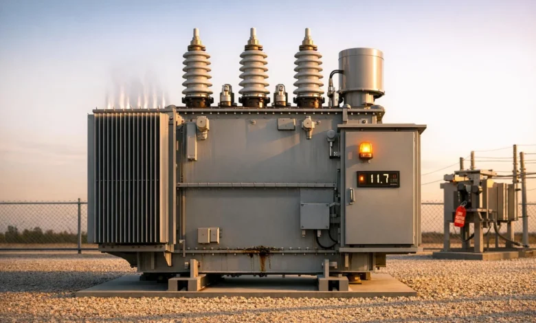

Oil filled power transformers fail for physical reasons, not at random. Heat, moisture, electrical stress, and mechanical forces gradually weaken paper insulation, oil, bushings, and tap changers. Because that degradation often leaves fingerprints long before a tank rupture or fire, operations and maintenance teams can spot risk in everyday data: dissolved gas analysis, thermal scans, bushing tests, acoustic monitoring, and protection records. The challenge is turning those signals into timely action. This article outlines practical indicators that a substation transformer is heading toward trouble, how those indicators relate to real failure modes, and what protective and containment steps reduce the chance that an internal fault becomes a fire.
-
Gas and Discharge Telltales Inside the Tank
Before diving into specific diagnostics, it helps to understand what causes a transformer to blow. Internal arcing, thermal decomposition of insulation, and sudden pressure rises are common triggers, and each leaves a chemical or electrical signature. Dissolved gas analysis, or DGA, looks for hydrogen, methane, ethane, ethylene, acetylene, and carbon monoxide in the oil. Rising acetylene suggests high-energy arcing; elevated CO and CO2 point to overheating paper insulation; persistent hydrogen can indicate partial discharge. Trend the rate of change rather than reacting to a single sample, and correlate spikes with load, ambient temperature, and switching events to separate normal inrush from emerging faults.
Partial discharge and incipient arcing can also be detected with acoustic sensors on the tank or high-frequency methods at bushings. PD activity that appears only under elevated voltage or load warns that local insulation strength is falling. A realistic example: an on-load tap changer shows small but steady acetylene increases over three samples. Acoustic checks localize activity to the OLTC compartment. Crews schedule an inspection, find carbonized contacts, and replace them before debris escalates into a through fault.
-
Thermal Red Flags in Cooling and Windings
Loss of cooling moves a transformer toward failure by accelerating insulation aging and inviting gas formation. Simple checks matter. Verify radiator fans and oil pumps start at the programmed top oil temperatures. Use infrared thermography to scan radiator headers, flange joints, tap changer selector covers, and bushing terminals. A single cold radiator among warm neighbors can indicate a stuck valve; a hot bushing terminal may point to a loose connector. Elevated top oil and hotspot temperatures increase moisture migration and can create bubbles that lower dielectric strength, making winding-to-ground faults more likely under stress.
Do not shrug off noisy fans or a pump that occasionally fails to start, because intermittent cooling can push hotspot temperatures past limits during a summer peak. Consider the trade off during emergencies: running hotter to serve load may be unavoidable, but document the thermal exposure and schedule follow-up DGA and insulation testing. A short term gain in megawatts can cost months of insulation life if repeated without mitigation.
-
Vulnerable Interfaces: Bushings, Tap Changers, and Leads
Many catastrophic events start at interfaces that are accessible to routine inspection. High voltage bushings deserve regular power factor and capacitance testing, plus visual checks for oil leaks, porcelain cracking, and surface contamination that promotes tracking. An on load tap changer’s diverter switch experiences mechanical wear and switching arcs; carbonized oil, degraded seals, and worn contacts lower dielectric margins. Winding leads and clamping can loosen after through faults, increasing local heating at braze joints or connection pads. Together, these weak points can create a path for partial discharge that evolves into arcing.
Consider a storm that produces several line faults and a transformer differential trip that clears quickly. The unit is returned to service, but the next monthly test shows a bushing power factor trending upward. Rather than waiting for an alarm, the team schedules an outage, and ultrasonic checks find internal bushing defects. Replacing the bushing removes a likely ignition source.
System Stresses and Protection That Shape Risk
The grid around a transformer can push it toward its limits. Frequent through faults impose high mechanical forces that loosen windings. Harmonic-rich loads from converters or heavily loaded capacitor banks raise stray losses and hotspot temperatures in the core and windings. Overexcitation during undervoltage conditions elevates flux density and heat. Frequent switching creates repeated inrush that stresses paper insulation. These stresses often show up indirectly: higher than expected no load losses, rising hotspot temperatures at similar loads, or incremental gas generation after disturbance events.
Protection and controls can be early witnesses to trouble. Sudden pressure relays, Buchholz relays on conservator-type units, and pressure relief devices can trip quickly as internal faults develop. Differential relays record disturbance magnitude and clearing times. Recurrent nuisance differential operations or unexplained restraint can hint at CT saturation or internal conditions worth investigating. Relay settings involve an unavoidable trade off: greater sensitivity improves fault detection, but poor coordination and excessive sensitivity can trip on benign events. After any misoperation, test trip coils, isolation valves, and communication paths to ensure real faults will clear quickly.
If Prevention Fails: Containment and Fire Planning That Works
Even with vigilant monitoring, a fault can progress into a tank rupture and fire if energy release outpaces relief devices. Physical design choices limit the consequences. Oil containment pits and flame arresting drains capture burning fluid. Firewalls or blast walls between units, noncombustible separation from control buildings, and firestopped cable trays reduce fire spread. Fixed water spray or deluge systems can cool tank surfaces to prevent reignition, while remote operated disconnects and switches let crews isolate equipment from a safe distance. Pre fire plans should map hydrants, foam supplies, and access routes that keep responders outside likely blast trajectories.
After any abnormal event, treat forensics as part of risk reduction. Sample and analyze oil promptly to see whether gases reflect arcing or simple overheating. Inspect bushings and cable terminations for tracking. If you used a deluge or hose stream, check glands, control cabinets, and nearby cable for water intrusion before reenergizing. Update maintenance logs with temperature, gas, and protection data from the incident, and fold the lessons into asset strategies. When teams connect chemical signatures, thermal evidence, interface condition, and protection behavior, they move from reacting to failures to preventing fires that start inside the tank.