Planning a 50 Foot Refrigerant Run: When a 7/8 x 3/8 Insulated Lineset Fits and How to Design It Right

Running refrigerant tubing across a property involves more than simply measuring the distance. Line diameter, insulation, routing, and elevation can all affect capacity, efficiency, and compressor reliability. A common configuration for larger residential and light commercial split systems is a 7/8-inch suction line paired with a 3/8-inch liquid line. At 50 feet, that combination can be practical, but only when it matches the equipment manufacturer’s requirements and is installed with careful attention to oil return, pressure drop, and contamination control. This article explains when a 7/8 x 3/8, 50-foot insulated lineset makes sense, what tradeoffs it introduces, and how proper routing, connections, and commissioning help the system perform as intended.
-
Where a 7/8 x 3/8, 50 Foot Lineset Belongs
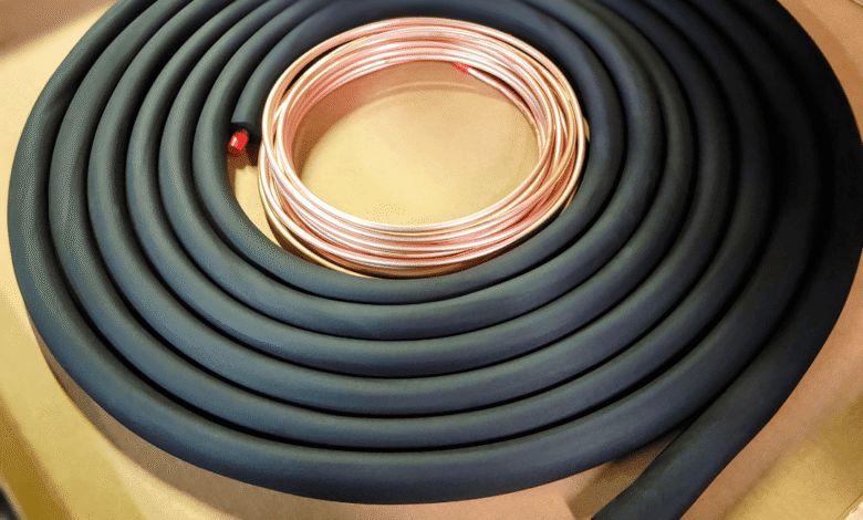
On larger-capacity heat pumps and central air conditioners using refrigerants such as R-410A or R-32, a 7/8-inch suction tube can help limit pressure drop over moderate distances. In comparison, a 3/8 inch liquid tube can support stable liquid refrigerant flow to the metering device. In practice, installers may use a preinsulated assembly of this size for runs between an outdoor condenser and an attic, closet, basement, or crawlspace air handler. For a precut option, some applications may use a 7/8 3/8 line set 50 ft when the equipment combination and manufacturer specifications support those diameters and that length. Always confirm tubing dimensions using the equipment manufacturer’s engineering data rather than assuming a particular size will suit every system.
-
Length, Elevation, and Oil Return on Vertical Risers
Fifty feet of installed tubing does not always equal 50 feet of effective refrigerant travel. Elbows, bends, fittings, and other restrictions add resistance to the system. As equivalent length increases, pressure losses may rise, and system capacity or efficiency can be affected. A larger suction tube can reduce pressure drop, but it also lowers refrigerant velocity. If velocity becomes too low, oil return to the compressor may become less reliable, particularly on long vertical sections.
For that reason, consider total length and elevation together. Vertical lifts, equipment location, refrigerant type, compressor design, and manufacturer requirements can all influence the appropriate line size and piping arrangement. Some systems may require additional oil management provisions for significant vertical risers, while others use different piping strategies. Follow the equipment manufacturer’s instructions rather than a general rule.
Route horizontal tubing to avoid unnecessary low spots where oil or refrigerant can collect. If the liquid line passes through a hot attic or another high-temperature space, follow the system manufacturer’s insulation requirements. Longer refrigerant lines may also require an adjusted refrigerant charge, which should be calculated according to the unit’s published specifications.
-
Routing, Bending, and Protecting the Lineset
Clean routing helps reduce unnecessary restrictions and protects the tubing from physical damage. Large smooth bends are generally preferable to sharp direction changes because they reduce the risk of kinking the copper and adding resistance. Support tubing with suitable clamps or hangers that limit vibration and prevent copper from rubbing against framing, masonry, or other surfaces.
Properly sleeve or protect wall penetrations where required, and seal exterior openings with materials appropriate for the wall assembly and local building requirements. Outdoor refrigerant lines can also benefit from protective covers that shield copper and insulation from sunlight, weather, accidental impact, and other environmental exposure while keeping the installation accessible for future service.
Insulation is particularly important on the suction line. Continuous closed-cell insulation helps limit heat gain and prevents condensation from forming on cold tubing. Seams and joints should remain properly sealed so humid air cannot reach the copper. In hot attics or areas exposed to intense sunlight, insulation rated for those conditions can help reduce deterioration and unwanted heat transfer.
For example, in a two-story home with the condenser at ground level and the air handler in a very hot attic, limiting the tubing exposed to attic heat and protecting the suction line with appropriate insulation can improve system performance and reduce condensation problems.
-
Flare or Braze: Making and Protecting the Connections
The connection method depends on the equipment type and manufacturer requirements. Factory flared connections are common on many ductless systems, while conventional central systems may use brazed refrigerant joints. In either case, the connection must be clean, mechanically sound, and compatible with the refrigerant and equipment design.
Flared joints require properly prepared tubing, accurate flare dimensions, and proper tightening per manufacturer specifications. Brazed systems require professional procedures that limit internal oxidation and prevent contaminants from entering the refrigerant circuit. Keep refrigerant tubing capped or otherwise protected whenever it is open so moisture, dust, and debris cannot enter.
After assembling the piping, a qualified HVAC technician should perform the appropriate leak testing, evacuation, and charging procedures using equipment designed for the refrigerant system. These steps are critical because moisture, air, or debris left inside the circuit can interfere with refrigerant flow and contribute to compressor or metering device problems.
Select and install filter driers and other protective components according to the manufacturer’s instructions, especially when a system has been opened for repair or when equipment is being replaced.
-
Commissioning Checks and Long-Term Details That Pay Off
After installation, commission the system using the equipment manufacturer’s procedures. The technician may verify refrigerant charge, operating pressures, temperatures, airflow, and other performance indicators under stable operating conditions. Check superheat and subcooling where appropriate for the specific metering device and system design.
Inspect the suction line insulation for gaps, compressed sections, or areas where condensation could form. Also check the liquid line and service connections for signs of abnormal operation. Proper labeling where lines enter mechanical spaces can make future service easier, and leaving reasonable access around equipment can reduce the need to disturb walls or finished surfaces during later repairs.
Two examples show why these details matter. In a retrofit with a long basement-to-attic riser, documenting the refrigerant line route and any manufacturer-required piping features can help future technicians understand the installation. In a coastal environment, protective coverings and corrosion-resistant supports can reduce deterioration caused by salt, moisture, and sunlight.
Design the Lineset Around the Equipment
Choosing a 7/8 x 3/8 lineset for a 50-foot run works well only when the dimensions match the equipment manufacturer’s requirements. Line sizing, equivalent length, elevation, refrigerant type, insulation, and service access must be considered together.
Proper routing and protection preserve the tubing’s physical condition, while clean, professional connections help keep contamination out of the refrigerant circuit. Careful commissioning then verifies that the system is operating within its intended range.
When these details are handled correctly, a 50-foot refrigerant run can support reliable cooling and heating without unnecessary pressure losses or service problems. Designing around the equipment specifications from the beginning also leaves a cleaner and more accessible installation for the technician who maintains the system in the future.